
리퍼비시 계측기
리퍼비시 계측기
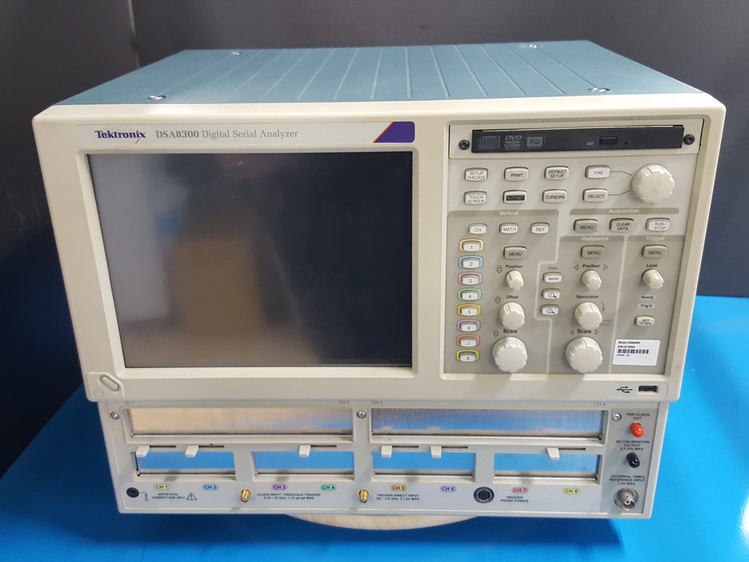
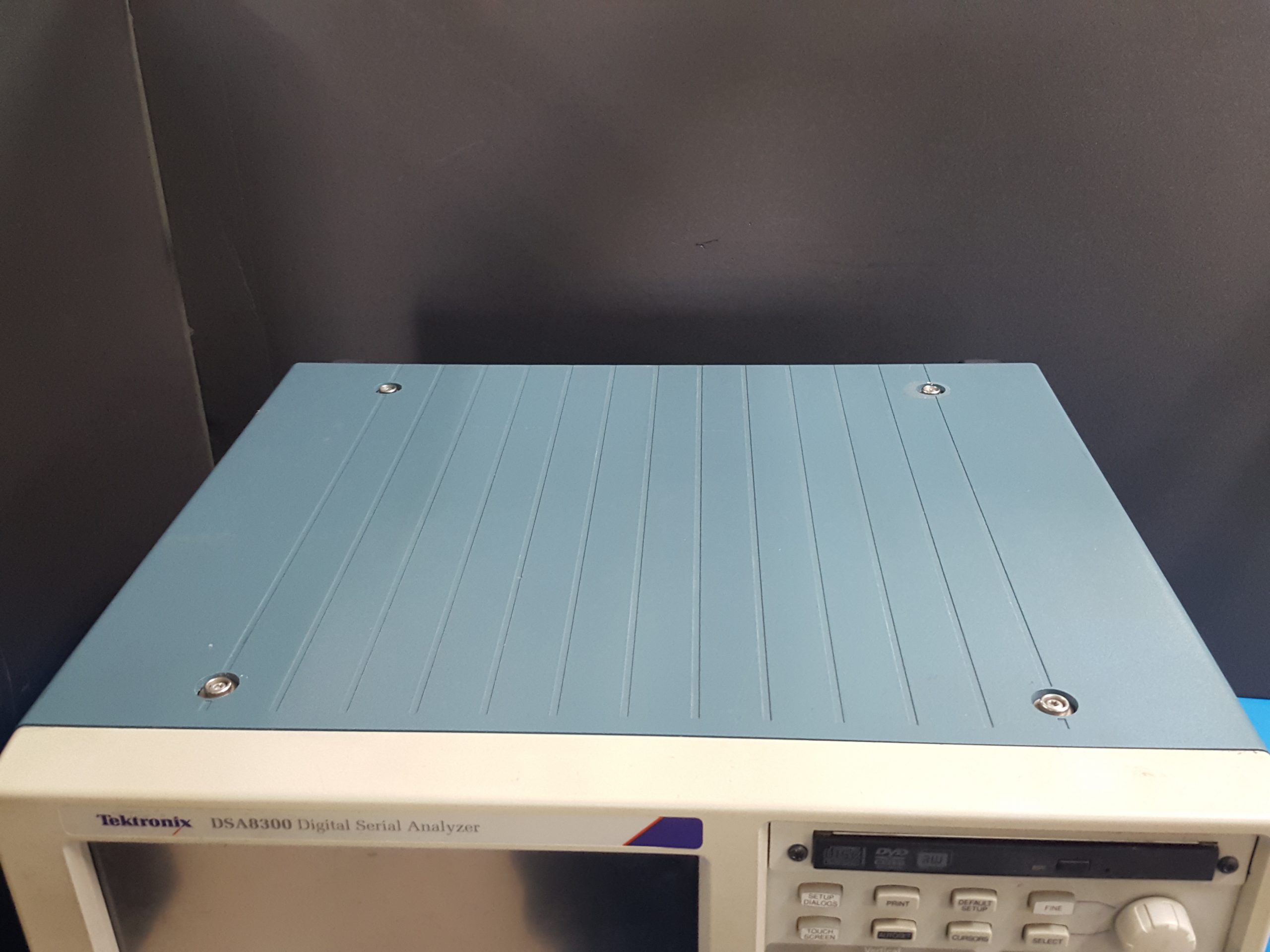
DSA8300
- ModelDSA8300
- MakerTektronix
- DescriptionDigital Serial Analyzer Sampling Oscilloscope
- Rental문의요망
- Stock문의요망
The DSA8300 is a state-of-the-art Equivalent Time Sampling Oscilloscope that provides the highest fidelity measurement and analysis capabilities for Communications Signal Analysis, Serial Data Network Analysis, and Serial Data Link Analysis applications.
Notice to EU customers
This product is not updated to comply with the RoHS 2 Directive 2011/65/EU and will not be shipped to the EU. Customers may be able to purchase products from inventory that were placed on the EU market prior to July 22, 2017 until supplies are depleted. Tektronix is committed to helping you with your solution needs. Please contact your local sales representative for further assistance or to determine if alternative product(s) are available. Tektronix will continue service to the end of worldwide support life.
Key performance specifications
- Low time base jitter:
- 425 fs typical on up to 8 simultaneously acquired channels
- <100 fs on up to 6 channels with 82A04B phase reference module
- Industry’s highest vertical resolution – 16 bit A/D
- Electrical resolution: <20 µV LSB (for 1 v full range)
- Optical resolution from <20 nW for the 80C07B (1 mW full range) to <0.6 µW for the 80C10C (30 mW full range)
- Optical bandwidths to >80 GHz
- Electrical bandwidths to >70 GHz
- Over 120 automated measurements for NRZ, RZ, and pulse signal types
- Automated mask testing with over 80 industry-standard masks
- Complex jitter/noise/BER/SER analysis (80SJNB), support for complex measurements TDECQ 1, SNDR 2 (applications)
1Transmitter and Dispersion Eye Closure Quaternary for PAM4.
2Signal-to-Noise-and-Distortion Ratio.
Key features
A wide variety of optical, electrical, and accessory modules support your specific testing requirements.
- Optical modules
- Optical modules that support optical data rates from 155 Mb/s to 10 Gb/s to 40 Gb/s to 100 Gb/s to PAM4 for 50G/100G/200G/400G
- Optical reference receivers (ORR) 1 support specified requirements for standards-mandated compliance testing
- High optical sensitivity, low noise, and wide dynamic range of the optical sampling modules allows accurate testing and characterization of short-reach to long-haul optical communications standards
- Fully calibrated clock recovery solutions – no need to manually calibrate for data pick-off losses
- Calibrated extinction ratio measurements and variable correction ER measurement ensure accuracy and repeatability
- Electrical modules
- Very low-noise electrical samplers (280 μV at 20 GHz, 450 μV at 60 GHz, typical)
- Selectable bandwidths 2 allow the user to trade-off sampler bandwidth and noise for optimal data acquisition performance
- Remote samplers or compact sampling extender module cables minimize signal degradation by allowing the sampler to be located in close proximity to the device under test
- High-performance integrated TDR (10 ps typical step rise time) supports exceptional impedance discontinuity characterization and high dynamic range for S-parameter measurements to 50 GHz
- Analysis
- Jitter, noise, and BER analysis of high-speed PAM4 and PAM2 NRZ serial data rates from <1 GBd to 60 GBd provides insight into precise causes of eye closure
-
Analysis of PAM4 signals with comprehensive jitter, noise and BER analysis for each individual PAM eye, and a set of global measurements that assess the overall PAM4 signal attributes
- 100G-SR4/Transmitter and Dispersion Eye Closure (TDEC) automation provides turn-key testing and debug of TX Optical properties key to the SR4 Short Reach Ethernet
- 80STDEC streamlines high performance Transmitter and Dispersion Eye Closure (TDEC) measurement making it ideal for manufacturing and conformance validation applications
- Automated mask testing with over 80 industry-standard masks. New masks can be imported into the DSA8300 to support new emerging standards. Users can define their own masks for automated mask testing
- Jitter, noise, BER, mask testing, and Serial Data Link Analysis (SDLA) are provided through the 80SJNB Essentials and Advanced Software Application Options
- Advanced TDR analysis, S-parameter measurements, simulation model extraction, and serial link simulation capabilities are provided by the IConnect® Software Application options
- 400G-M4 Optical Manufacturing Analysis Software provides Optical Transmitter and Dispersion Eye Closure Quaternary (TDECQ) analysis
- High test throughput
- High sample acquisition rate up to 200 kS/s per channel
- Efficient programmatic interface (IEEE-488, Ethernet, or local processor access) enables high test throughput
1Optical Reference Receiver (ORR) is a 4th-order Bessel-Thompson filter, with a frequency response and tolerances as defined by the standards. Tektronix optimizes the response for best nominal fit and highest quality mask test results.
2Refer to the 80E00 Electrical Sampling Modules datasheet for detailed descriptions of each available module.
Applications
- Design/Verification of telecom and datacom components and systems
- Manufacturing/testing for ITU/ANSI/IEEE/SONET/SDH compliance
- High-performance true-differential TDR measurements
- Impedance characterization and network analysis for serial data applications including S-parameters
- Advanced jitter, noise, BER and SDLA analysis
- Channel and eye diagram simulation and measurement-based modeling with IConnect.
Superior performance with extraordinary versatility
The DSA8300 Digital Serial Analyzer is the most versatile tool for developing and testing communications, computers, and consumer electronics which use multi-gigabit data transmission. It is used for optical and electrical transmitter characterization, as well as compliance verification for devices, modules, and systems used in these products.
In addition, the DSA8300 is well-suited for electrical signal path characterization, whether for packages, PCBs, or electrical cables. With exceptional bandwidth, signal fidelity, and the most extensible modular architecture, the DSA8300 provides the highest-performance TDR and interconnect analysis, most accurate analysis of signal impairments, and BER calculations for current and emerging serial data technology.
Optical eye diagram testing

Passive interconnect test
Finally, with its exceptional signal fidelity and resolution, the DSA8300 is the gold standard for electrical and optical applications which require ultra-high bandwidths, very fine vertical resolution, low jitter, and/or exceptionally low noise.
The DSA8300 provides unmatched measurement system fidelity with the lowest native instrument jitter floor (425 fs RMS, typical for serial data signals at rates >1.25 Gb/s) that ensures the most accurate acquisition of up to 8 high-bandwidth signals simultaneously. You get additional analysis benefits from acquisition jitter below 100 fs RMS when using the 82A04B Phase Reference module.
The multiprocessor architecture, with dedicated per-slot digital signal processors (DSPs), provides fast waveform acquisition rates, reducing the test times necessary for reliable characterization and compliance verification.
The DSA8300’s versatile modular architecture supports a large and growing family of plug-ins enabling you to configure your measurement system with a wide variety of electrical, optical, and accessory modules that best suit your application now and in the future. With 6 module slots, the DSA8300 can simultaneously accommodate a Clock Recovery module, a precision Phase Reference module, and multiple acquisition modules (electrical or optical), so you can match system performance to your evolving needs. The ability to swap sampling modules without powering down the DSA8300 (available for scopes with firmware versions 6.1 and later) provides additional flexibility in configuring your DSA8300 to changing test needs.
In addition, specialized modules supporting features such as single-ended and differential electrical clock recovery, electrostatic protection for electrical samplers, and connectivity to the popular TekConnect®probing system brings you the performance of state-of-the-art Tektronix probes for high-impedance and differential probing. Low-impedance probes for 50 Ω probing and for TDR probing are also available.
The raw acquisition performance of the DSA8300 and its sampling modules and accessories is further augmented by the comprehensive measurement and analysis capabilities of the DSA8300 and its associated software applications.
See the Ordering information for a list of currently available software applications and modules.
Measurement and analysis tools for optical testing applications
The DSA8300 includes a wide variety of measurement and analysis tools which specifically address optical testing applications. In addition to the standard amplitude and timing parametric measurements (such as rise/fall times, amplitude, RMS jitter, RMS noise, frequency, period, and so on), the measurement suite for the DSA8300 includes measurements specifically tailored to measuring optical signals (average optical power, extinction ratio, eye height, eye width, optical modulation amplitude (OMA), and so on). For a complete list of measurements, see theMeasurementsection of this datasheet.
The DSA8300 also includes standard compliance testing masks for all of the common optical standards from 155 Mb/s to 100 Gb/s. The DSA8300 mask testing system includes the ability to automatically fit standard and user masks to data acquired into a waveform database. The mask test system can also automatically determine the mask margin based either on the total number of mask violations or the “hit ratio” of mask violation to the number of samples acquired in the mask test unit interval. Users can also create custom masks for automated mask testing. Histograms and cursor measurements are also available to analyze optical signals acquired by the DSA8300.
Test solutions
The DSA8300, with its highly configurable mainframe and a wide variety of modules, provide complete test solutions with superior system fidelity.
- Optical modules
The Tektronix 80C00 family of optical sampling modules cover a range of wavelengths for both single- and multi-mode fibers. The various modules provide a range of features such as clock recovery, reference receiver filters, and a wide range of standards test solutions.
Refer to the Ordering information section for a list of currently available optical modules.
Refer to the 80C00 Optical Modules datasheet for detailed descriptions of each available module.
- Electrical modules
The Tektronix 80E00 family of electrical sampling modules provide a wide variety of capabilities, allowing the user to configure a test solution specifically adapted to their application. A wide variety of bandwidth solutions is available along with other features such as Time Domain Reflectometry or S-parameter testing.
Refer to the Ordering information section for a list of currently available electrical modules.
Refer to the 80E00 Electrical Sampling Modules datasheet for detailed descriptions of each available module.
- Utility modules
The Tektronix 80A00 and 82A00 families of modules provide additional capabilities such as phase reference and ESD protection.
Refer to the Ordering information section for a list of currently available utility type modules.
Refer the to the various utility module datasheets for detailed descriptions of each available module.
- 80A02 EOS ESD Isolation Module
- 82A04B Phase Reference Module
- 80A03 module extender
80B28G – a DSA8300 product bundle for 28 Gb/s applications
This bundle, when used with a DSA8300, provides all of the electrical sampling modules, accessories, and clock recovery capabilities needed to test applications at rates from 10 Gb/s to 28.6 Gb/s per lane. The bundle includes the following products:
- 1 ea. 80E09B: dual channel, 70 GHz Remote Electrical Sampling Module
- 1 ea. 82A04B: Phase Reference Module that supports sub-100 fs instrumentation jitter when used with the 80E09B
- 1 ea. CR286A with Option HS: 28.6 GHz clock recovery instrument that supports clock recovery at rates from 150 Mb/s to 28.6 Gb/s
- 1 ea. 80X01: 1-meter sampling module extender cable used to extend the phase reference module to connect directly to the clock recovery module
- 1 ea. 80A08 : accessory kit with all of the necessary cables, adapters, DC blocks and other accessories to configure a complete test solution
To extend this solution to test additional lanes in a multi-lane application, simply install additional 80E09B dual channel remote sampling modules.
Product specifications and descriptions in this document are subject to change without notice.
All specifications are guaranteed unless noted otherwise. All specifications apply to all models unless noted otherwise.
Vertical system
- Rise Time / Bandwidth
- Determined by the sampling modules used
- Vertical Resolution
-
16 bits over the sampling modules’ dynamic range
Electrical Resolution: <20 μV LSB (for 1 V full range)
Optical resolution depends on the dynamic range of the optical module – ranges from <20 nW for the 80C07B (1 mW full range) to <0.6 μW for the 80C10C (30 mW full range)
Horizontal system
- Main and Magnification View Time Bases, Horizontal Scale
- 100 fs/div to 1 ms/div, in 1-2-5 sequence or 100 fs increments
- Time Interval Accuracy
-
- Trigger Direct (Front Panel) Input
-
Horizontal scale >20 ps/div, right-most point of measurement interval <150 ns; Mean Accuracy: 0.1% of interval, STDEV: ≤1 ps
Horizontal scale ≤20 ps/div, right-most point of measurement interval <150 ns; Mean Accuracy: 1 ps + 0.5% of interval
- Clock Input/Prescale Trigger (Front Panel), Eye or Pattern Mode
- Mean accuracy determined by clock input accuracy STDEV: <0.7 ps (max); <0.1 ps (typical)
- Clock Input/Prescale Trigger (Front Panel), Other Mode
-
Horizontal scale >20 ps/div, right-most point of measurement interval <150 ns; Mean Accuracy: 0.1% of interval, STDEV: ≤3 ps
Horizontal scale ≤20 ps/div, right-most point of measurement interval <150 ns; Mean Accuracy: 1 ps + 0.5% of interval
- TDR Clock Trigger (Lock to External 10 MHz Clock)
- Horizontal scale >20 ps/div, right-most point of measurement interval <150 ns; Mean Accuracy: 0.01% of interval, STDEV: ≤1 ps (0.1 ps typical)
- Random Phase Corrected Mode (Clock Input to 82A04B)
-
Maximum timing deviation 0.1% of phase reference signal period, typical, relative to phase reference signal
For more information on phase reference modes of operation, see the “Phase Reference Module for the DSA8300 Sampling Oscilloscope” datasheet.
- Triggered Phase Corrected Mode (Clock Input to 82A04B)
-
Maximum timing deviation relative to phase reference signal:
>40 ns after trigger event: 0.2% of phase reference signal period, typical
≤40 ns after trigger event: 0.4% of phase reference signal period, typical
- Horizontal Deskew Range Available
-
SW: –500 ps to +100 ns on any individual channel in 100 fs increments, some limitations apply to software deskew TDR and sampling modules. Note that SW deskew implies acquiring another waveform, at a different horizontal position; a throughput penalty exists.
Mainframe channel delay (HW deskew):
Sample mode:
80E11 and 80E11x1: ±35 ps
80E07B, 80E08B, 80E09B, and 80E10B: ±150 ps
80C17, 80C18: +/- 65 ps
TDR mode:
80E08B and 80E10B: ±200 ps
- DSA8300 Record Length
- 50, 100, 250, 500, 1000, 2000, 4000, 8000, or 16000 samples (magnification views have maximum record length of 4000 samples)
- Longer Records Available
-
IConnect®: 1M samples
80SJNB Jitter, Noise, and BER Analysis Software: 10M samples (100k unit intervals, 100 samples per unit interval)
Trigger system
- Trigger Sources
-
Clock Input/Prescale Trigger (front panel)
TDR clock (generated internally)
Clock recovery triggers from Optical Sampling modules and Electrical Clock Recovery modules (internally connected)
Phase Reference (when using the 82A04B Phase Reference module) time base supports acquisitions without a trigger signal in its Free Run mode
Trigger Direct Input (front panel)
- Clock Input / Prescale Trigger Input
-
- Clock Input Sensitivity
-
150 mVp-pto 1 Vp-p, 0.15 GHz to 20 GHz (typical)
200 mVp-pto 1 Vp-p, 0.8 GHz to 15 GHz (guaranteed)
- Minimum Slew Rate
- ≥2 V/ns
- Clock Input Range
- 1.0 Vp-p (max) – AC coupled
- Pattern Lengths Supported (for Pattern Triggering with ADVTRIG Option)
- 2 to 223 (8,388,608) inclusive
- Clock Input Jitter in Clock-eye and Clock-pattern Trigger Modes (Typical)
-
0.15 – 0.40 GHz: 900 fs (RMS)
0.40 – 1.25 GHz: 800 fs
1.25 – 20 GHz: 425 fs
- Clock Input Jitter in Clock-eye and Clock-pattern Trigger Modes (Max)
-
0.80 – 1.25 GHz: 900 fs (RMS)
1.25 – 11.20 GHz: 500 fs
11.20 – 15.0 GHz: 600 fs
- TDR Trigger
-
- TDR Step Rate
-
Selectable from 25 to 300 kHz in 1 kHz steps
Actual TDR step rate may vary up to 2% from requested rate
- TDR Trigger Jitter
- 1.3 ps RMS (typical) 1.8 ps RMS (max)
- Phase Reference Time Base
-
- Phase Reference Input Range
-
Standard 82A04B: 8 – 32 GHz (guaranteed), 2 – 32 GHz (typical)
82A04B Option 60G: 8 – 60 GHz (guaranteed), 2 – 70 GHz (typical)
For non-sinusoidal clock at frequencies <8 GHz, it may be necessary to filter the clock input to eliminate harmonics from the clock signal (see accessories 020-2566-xx, 020-2567-xx, and 020-2568-xx)
- Phase Reference Input Sensitivity
- Best jitter performance is with the clock input to the 82A04B in the following range: 0.6 – 1.8 V. The phase reference time base remains operational to 100 mV (typical) with increased jitter
- Jitter
-
f ≥8 GHz: 100 fs RMS, on a 10 GHz or faster sampling module
2 GHz ≤ f ≤ 8 GHz: 140 fs RMS, typical on a 10 GHz or faster acquisition module
- Trigger Direct Input
-
- Trigger Sensitivity
-
50 mV, DC – 4 GHz (typical)
100 mV, DC – 3 GHz (guaranteed)
- Trigger Level Range
- ±1.0 V
- Trigger Input Range
- ±1.5 V
- Trigger Holdoff
- Adjustable 5 μs to 50 ms in 0.5 ns increments
- Trigger Direct Input Jitter
-
1.1 ps RMS + 5 ppm of horizontal position (typical)
1.5 ps RMS + 10 ppm of horizontal position (max)
Acquisition system
- Acquisition modes
- Sample (Normal), Envelope, and Average
- Number of sampling modules accommodated
-
Up to 4 dual-channel electrical; up to 2 optical sampling modules.
Population of the CH1/CH2 large slot with any module other than one requiring power only displaces functionality of the CH1/CH2 small slot; population of the CH3/CH4 large slot with any module other than one requiring power only displaces functionality of the CH3/CH4 small slot.
- Number of simultaneously acquired inputs
- 8 channels maximum
- Maximum acquisition rate
-
300 kS/s per channel in TDR mode
200 kS/s per channel in all other nonphase reference modes
120 kS/s per channel in phase reference modes
Waveform measurements
- System Measurement Rate
- The DSA8300 supports up to 8 simultaneous measurements, updated 3 times per second with optional display of per-measurement statistics (min, max, mean, and standard deviation)
- Measurement Set
- Over 120 automated measurements include RZ, NRZ, and pulse signal types, and the following measurement types:
- Amplitude Measurements
- High, Low, Amplitude, Peak-to-Peak, Max, Mid, Min, Mean, +Overshoot, –Overshoot, P-P, Average Optical Power (dBm, watts), Noise, RMS Noise, SNR, Eye Height, Eye Opening Factor, Extinction Ratio (Ratio, %, dB), Suppression Ratio (Ratio, %, dB), OMA, Q-factor, RMS, AC RMS, Cycle RMS, Cycle Mean, Gain, Crossing %, Crossing Level OMA, VMA
- Timing Measurements
- Rise, Fall, Period, Bit Rate, Bit Time, Frequency, Crossing Time, +Cross, –Cross, Jitter (P-P, RMS), Eye Width, +Width, –Width, Burst Width, +Duty Cycle, –Duty Cycle, Duty Cycle Distortion, Delay, Phase, Pulse Symmetry
- Area Measurements
- Area, Cycle Area
- Cursors
- Dot, vertical bar, and horizontal bar cursors
- Waveform Processing
- Up to 8 math waveforms can be defined and displayed using the following math functions: Add, Subtract, Multiply, Divide, Average, Differentiate, Exponential, Integrate, Natural Log, Log, Magnitude, Min, Max, Square Root, and Filter. In addition, measurement values can be utilized as scalars in math waveform definitions
- Mask Testing
- For many applications, standard masks are available as predefined, built-in masks. Many of the most commonly used standard masks are shown in the following supported standards list. Contact your local Tektronix representative to get a list of all available masks. Unless otherwise noted, file-based masks are used to distribute new, Tektronix factory-created, updated masks as a file loadable by the firmware. User-defined masks allow the user to create (through UI or PI) user masks