리퍼비시 계측기
리퍼비시 계측기
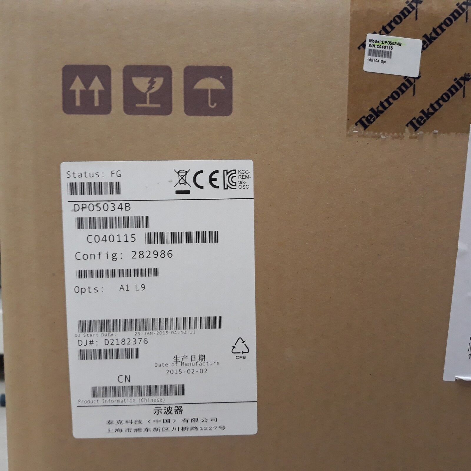
DPO5034B
- ModelDPO5034B
- MakerTektronix
- DescriptionOscilloscope; Digital Phosphor, 350MHz, 5GS/s
- Rental문의요망
- Stock문의요망
Oscilloscope; Digital Phosphor, 350MHz, 5GS/s
odel overview
|
MSO5034B DPO5034B |
MSO5054B DPO5054B |
MSO5104B DPO5104B |
MSO5204B DPO5204B |
||
|---|---|---|---|---|---|
| Input Channels | 4 | ||||
| Bandwidth | 350 MHz | 500 MHz | 1 GHz | 2 GHz | |
| Rise Time (Calculated) | 1 ns | 700 ps | 350 ps | 175 ps | |
| DC Gain Accuracy | ±1.5%, derated at 0.10%/°C above 30 °C | ||||
| Bandwidth Limits | Depending on instrument model: 1 GHz, 500 MHz, 350 MHz, 250 MHz, and 20 MHz | ||||
| Effective Number of Bits (Typical) | 6 bits (10 divisionp-p sine wave input at instrument bandwidth, 100 mV/div, 50 Ω Input Impedance, maximum sample rate, 1 k point record length) | ||||
| Random Noise (RMS, typical, sample mode, full BW, 50 Ω) | |||||
| 1 mV/div | 173 μV | 178 μV | 68 μV | 70 μV | |
| 2 mV/div | 216 μV | 236 μV | 128 μV | 158 μV | |
| 5 mV/div | 231 μV | 281 μV | 214 μV | 307 μV | |
| 10 mV/div | 305 μV | 340 μV | 315 μV | 485 μV | |
| 20 mV/div | 504 μV | 523 μV | 547 μV | 791 μV | |
| 50 mV/div | 1.15 mV | 1.17 mV | 1.29 mV | 1.82 mV | |
| 100 mV/div | 2.40 mV | 2.46 mV | 3.08 mV | 4.75 mV | |
| 1 V/div | 22.96 mV | 22.98 mV | 23.15 mV | 29.58 mV | |
| Maximum Sample Rate (All channels) | 5 GS/s | 5 GS/s | 5 GS/s | 5 GS/s | |
| Maximum Sample Rate (1 or 2 channels) | 5 GS/s | 5 GS/s | 10 GS/s | 10 GS/s | |
| Maximum Equivalent Time Sampling Rate | 400 GS/s | ||||
| Maximum Record Length with Standard Configuration | 25 M | 25 M (4 ch) 50 M (1 or 2 ch) |
|||
| Maximum Record Length with Option 5RL | 50 M | 50 M (4 ch) 125 M (1 or 2 ch) |
|||
| Maximum Record Length with Option 10RL | 125 M | 125 M (4 ch) 250 M (1 or 2 ch) |
|||
Vertical system analog channels
- Input coupling
- AC, DC
- Input resistance
- 1 MΩ ±1%, 50 Ω ±1%
- Input sensitivity range
-
1 MΩ: 1 mV/div to 10 V/div
50 Ω: 1 mV/div to 1 V/div
- Vertical resolution
- 8 bits (>11 bits with Hi Res)
- Maximum input voltage, 1 MΩ
-
300 VRMSCAT II, with peaks ≤ ±425 V
For <100 mV/div derate at 20 dB/decade above 100 kHz to 30 VRMSat 1 MHz, 10 dB/decade above 1 MHz
For ≥100 mV/div derate at 20 dB/decade above 3 MHz to 30 VRMSat 30 MHz, 10 dB/decade above 30 MHz
- Maximum input voltage, 50 Ω
- 5 VRMS, with peaks ≤ ±20 V
- Position range
- ±5 divisions
- Delay between any Two Channels (Typical)
-
≤100 ps (50 Ω, DC coupling and equal V/div at or above 10 mV/div)
- Offset range
-
- 1 mV/div – 50 mV/div
-
1 MΩ: ±1 V
50 Ω: ±1 V
- 50.5 mV/div – 99.5 mV/div
-
1 MΩ: ±0.5 V
50 Ω: ±0.5 V
- 100 mV/div – 500 mV/div
-
1 MΩ: ±10 V
50 Ω: ±10 V
- 505 mV/div – 995 mV/div
-
1 MΩ: ±5 V
50 Ω: ±5 V
- 1 V/div – 5 V/div
-
1 MΩ: ±100 V
50 Ω: ±5 V
- 5.05 V/div – 10 V/div
-
1 MΩ: ±50 V
50 Ω: NA
- Offset Accuracy
-
±(0.005 × |offset – position| + DC Balance)
Note: Both position and constant offset term must be converted to volts by multiplying by the appropriate volts/div term
- Channel-to-channel isolation (Any two channels at equal vertical scale settings) (typical)
-
≥100:1 at ≤100 MHz and ≥30:1 at >100 MHz up to the rated BW
Vertical system digital channels
- Input Channels
- 16 Digital (D15 – D0)
- Thresholds
- Per-channel Thresholds
- Threshold Selections
- TTL, ECL, User
- User-defined Threshold Range
-
±40 V
- Threshold Accuracy
- ±(100 mV + 3% of threshold setting)
- Maximum Input Voltage
- ±42 Vpeak
- Input Dynamic Range
-
30 Vp-p≤200 MHz
10 Vp-p>200 MHz
- Minimum Voltage Swing
- 400 mV
- Input Impedance
- 100 kΩ
- Probe Loading
- 3 pF
- Vertical Resolution
- 1 bit
Horizontal system analog channels
- Maximum Duration at Highest Real-Time Sample Rate
-
25 ms
- Time Base Range
- 12.5 ps/div to 8,000,000 s/div
- Time resolution (in ET/IT mode)
- 2.5 ps/div
- Time base delay time range
- –10 divisions to 1000 s
- Channel-to-channel deskew range
-
±75 ns
- Time base accuracy
- ±5 ppm over any ≥1 ms interval
Horizontal system digital channels
- Maximum Sample Rate (Main)
-
500 MS/s (2 ns resolution)
- Maximum record length (main)
-
25 M Standard
Up to 40 M with Record Length options
- Maximum sample rate (MagniVu)
-
16.5 GS/s (60.6 ps resolution)
- Maximum record length (MagniVu)
-
10k points centered around the trigger
- Minimum detectable pulse width
-
1 ns
- Channel-to-channel skew (typical)
-
200 ps
- Maximum input toggle rate
-
500 MHz at minimum input swing; higher toggle rates can be achieved at higher amplitudes
Trigger system
- Main trigger modes
- Auto, Normal, and Single
- Trigger coupling
-
DC, AC, HF Rej (attenuates >50 kHz), LF Rej (attenuates <50 kHz), Noise Reject (reduces sensitivity)
- Trigger holdoff range
- 250 ns to 8 s
- Enhanced triggering
-
User-selectable; corrects the difference in timing between the trigger path and the acquired data (not available in FastAcq)
- Trigger jitter
-
≤100 fsRMSusing Enhanced Trigger
≤10 psRMSwithout Enhanced Trigger and in Fast Acq mode
≤100 psRMSfor non-Edge-type trigger modes
- Trigger sensitivity
-
- Internal DC coupled
-
For 1 MΩ: 1 mV/div to 4.98 mV/div: 0.75 div from DC to 50MHz, increasing to 1.3 div at instrument bandwidth ≥5 mV/div: 0.40 div from DC to 50 MHz, increasing to 1 div at instrument bandwidth
For 50 Ω (MSO5204, DPO5204, MSO5104, DPO5104): 0.40 div from DC to 50 MHz, increasing to 1 div at instrument bandwidth
For 50 Ω (MSO5054, DPO5054, MSO5034, DPO5034): 1 mV/div to 4.98 mV/div: 0.75 div from DC to 50MHz, increasing to 1.3 div at instrument bandwidth ≥5 mV/div: 0.40 div from DC to 50 MHz, increasing to 1 div at instrument bandwidth
- External (auxiliary input) 1 MΩ
-
200 mV from DC to 50 MHz, increasing to 500 mV at 250 MHz
- Trigger level range
-
- Any channel
- ±8 divisions from center of screen
- External (auxiliary input)
- ±8 V
- Line
- Fixed at about 50% of line voltage
- Trigger modes
-
- Edge
- Positive, negative, or either slope on any channel or front-panel auxiliary input. Coupling includes DC, AC, HF reject, LF reject, and noise reject
- Glitch
- Trigger on or reject glitches of positive, negative, or either polarity. Programmable glitch width is 4 ns minimum to 8 s maximum
- Runt
- Trigger on a pulse that crosses one threshold but fails to cross a second threshold before crossing the first again
- Width
- Trigger on width of positive or negative pulse either within or outside selectable limits (4 ns to 8 s)
- Timeout
- Trigger on an event which remains high, low, or either, for a specified time period (4 ns to 8 s)
- Transition
- Trigger on pulse edge rates that are faster or slower than specified. Slope may be positive, negative, or either
- Setup/Hold
- Trigger on violations of both setup time and hold time between clock and data present on any two input channels
- Pattern
-
Trigger when any logical pattern of signals goes false or stays true for specified period of time (4 ns to 1 s). Pattern (AND, OR, NAND, NOR) specified for all analog and digital input channels defined as High, Low, or Don’t Care
- Parallel Bus
- Trigger on specified data value on defined parallel bus
- State
- Any logical pattern of analog channels and digital channels (MSO models) clocked by edge on another channel. Trigger on rising or falling clock edge
- Video
- Trigger on all lines, specific line number, odd, even, or all fields on NTSC, PAL, SECAM, and HDTV 480p/60, 576p/50, 875i/60, 720p/30, 720p/50, 720p/60, 1080/24sF, 1080i/50, 1080p/25, 1080i/60, 1080p/24, 1080p/25, 1080p/50, 1080p/60, Bi-level, Tri-level
- Trigger Sequences
-
Main, Delayed by Time, Delayed by Events. All sequences can include separate horizontal delay after the trigger event to position the acquisition window in time
- A/B Sequence Event Trigger Types
-
Edge
- Trigger Delay by Time
- 4 ns to 8 s
- Trigger Delay by Events
- 1 to 4,000,000 events
- Visual Trigger
-
Trigger on up to 8 user-specified areas, including rectangle, triangle, trapezoid, hexagon, and user-specified shapes on any of the analog channels
- I2C (Optional)
-
Provided as part of Opt. SR-EMBD. Trigger on Start, Repeated Start, Stop, Missing ACK, Address (7 or 10 bit), Data, or Address and Data on I2C buses up to 10 Mb/s
- SPI (Optional)
- Provided as part of Opt. SR-EMBD. Trigger on Slave Select, Idle Time, or Data (1-16 words) on SPI buses up to 10 Mb/s
- CAN (Optional)
-
Provided as part of Opt. SR-AUTO. Trigger on Start of Frame, Type of Frame (Data, Remote, Error, or Overload), Identifier, Data, Identifier and Data, EOF, Missing Ack, Bit Stuff Error, and CRC Error on CAN buses up to 1 Mb/s
- LIN (Optional)
-
Provided as part of Opt. SR-AUTO. Trigger on Sync, Identifier, Data, Identifier and Data, Wakeup Frame, Sleep Frame, and Error on LIN buses up to 1 Mb/s
- FlexRay (Optional)
-
Provided as part of Opt. SR-AUTO. Trigger on Indicator Bits (Normal, Payload, Null, Sync, Startup), Cycle Count, Header Fields (Indicator Bits, Identifier, Payload Length, Header CRC, and Cycle Count), Identifier, Data, Identifier and Data, End Of Frame, and Error on FlexRay buses up to 10 Mb/s
- MIL-STD-1553 (Optional)
-
Provided as part of Opt. SR-AERO. Trigger on Sync, Command Word, Status Word, Data Word, Idle Time, and Error on MIL-STD-1553 buses up to 1 Mb/s
- Ethernet (Optional)
-
Provided as part of Opt. SR-ENET. Trigger on Start of Packet, MAC Address, MAC Q-tag, MAC Length/Type, MAC Data, IP Header, TCP Header,
TCP/IPV4 Data, End of Packet, and FCS(CRC) Error on 10BASE-T and 100BASE-TX buses.
- RS-232/422/485/UART (Optional)
-
Provided as part of Opt. SR-COMP. Trigger on Start Bit, End of Packet, Data, and Parity Error up to 10 Mb/s
- USB 2.0 Low Speed: (Optional)
- Provided as part of Opt. SR-USB.
Trigger on Sync, Reset, Suspend, Resume, End of Packet, Token (Address) Packet, Data Packet, Handshake Packet, Special Packet, Error.
Token Packet Trigger – Any token type, SOF, OUT, IN, SETUP; Address can be specified for Any, OUT, IN, and SETUP token types. Address can be further specified to trigger on ≤, <, =, >, ≥, != a particular value, or inside or outside a range. Frame number can be specified for SOF token using Binary, Hex, Unsigned Decimal, and Don’t Care digits.
Data Packet Trigger – Any data type, DATA0, DATA1; Data can be further specified to trigger on ≤, <, =, >, ≥, != a particular data value, or inside or outside a range.
Handshake Packet Trigger – Any handshake type, ACK, NAK, STALL.
Special Packet Trigger – Any special type, Reserved.
Error Trigger – PID Check, CRC5 or CRC16, Bit Stuffing.
- USB 2.0 Full Speed: (Optional)
- Provided as part of Opt. SR-USB.
Trigger on Sync, Reset, Suspend, Resume, End of Packet, Token (Address) Packet, Data Packet, Handshake Packet, Special Packet, Error.
Token Packet Trigger – Any token type, SOF, OUT, IN, SETUP; Address can be specified for Any, OUT, IN, and SETUP token types. Address can be further specified to trigger on ≤, <, =, >, ≥, != a particular value, or inside or outside a range. Frame number can be specified for SOF token using Binary, Hex, Unsigned Decimal, and Don’t Care digits.
Data Packet Trigger – Any data type, DATA0, DATA1; Data can be further specified to trigger on ≤, <, =, >, ≥, != a particular data value, or inside or outside a range.
Handshake Packet Trigger – Any handshake type, ACK, NAK, STALL.
Special Packet Trigger – Any special type, PRE, Reserved.
Error Trigger – PID Check, CRC5 or CRC16, Bit Stuffing.
- USB 2.0 High Speed: (Optional)
- Provided as part of Opt. SR-USB.
Trigger on Sync, Reset, Suspend, Resume, End of Packet, Token (Address) Packet, Data Packet, Handshake Packet, Special Packet, Error.
Token Packet Trigger – Any token type, SOF, OUT, IN, SETUP; Address can be specified for Any, OUT, IN, and SETUP token types. Address can be further specified to trigger on ≤, <, =, >, ≥, != a particular value, or inside or outside a range. Frame number can be specified for SOF token using Binary, Hex, Unsigned Decimal, and Don’t Care digits.
Data Packet Trigger – Any data type, DATA0, DATA1, DATA2, DATAM; Data can be further specified to trigger on ≤, <, =, >, ≥, != a particular data value, or inside or outside a range.
Handshake Packet Trigger – Any handshake type, ACK, NAK, STALL, NYET.
Special Packet Trigger – Any special type, ERR, SPLIT, PING, Reserved. SPLIT packet components that can be specified include:
Hub Address
Start/Complete – Don’t Care, Start (SSPLIT), Complete (CSPLIT) Port Address
Start and End bits – Don’t Care, Control/Bulk/Interrupt (Full-speed Device, Low-speed Device), Isochronous (Data is Middle, Data is End, Data is Start, Data is All)
Endpoint Type – Don’t Care, Control, Isochronous, Bulk, Interrupt
Error Trigger – PID Check, CRC5, CRC16, Any.
Note: USB 2.0 High-speed triggering, decoding, and search only available on 1 GHz and 2 GHz models.
Acquisition system
- Acquisition modes
-
- Sample
- Acquire sampled values
- Peak detect
-
Captures narrow glitches as narrow as 100 ps (2 GHz and 1 GHz models) or 200 ps (500 MHz and 350 MHz models) at all real-time sampling rates
- Averaging
- From 2 to 10,000 waveforms included in average
- Envelope
-
Min-Max envelope reflecting Peak Detect data over multiple acquisitions
- Hi-Res
-
Real-time boxcar averaging reduces random noise and increases resolution
- Roll mode
-
Scrolls sequential waveform points across the display in a right-to-left rolling motion at sweep speeds slower than 50 ms/div. Up to 20 MS/s with a maximum record length of 10 M
- FastAcq®
-
FastAcq optimizes the instrument for analysis of dynamic signals and capture of infrequent events
- Maximum FastAcq waveform capture rate
-
>250,000 wfms/s on all 4 channels simultaneously
- Waveform database
-
Accumulate waveform database providing three-dimensional array of amplitude, time, and counts
- FastFrame™
-
Acquisition memory divided into segments; maximum trigger rate >310,000 waveforms per second. Time of arrival recorded with each event. Frame finder tool helps to visually identify transients
- Automated Search and Mark
-
Automatically mark events and document waveforms. Search positive/negative slopes or both, glitches, runts, pulse widths, transition rate, setup and hold, timeout, windows, or find any logic or state pattern, up to 8 different event types on any of the 4 analog channels. Search DDR Read or Write bursts with Opt. DDRA. Event table summarizes all found events. All events are time stamped in reference to trigger position. Stop acquisitions when an event is found
Waveform analysis
- Waveform measurements
-
- Cursors
-
Waveform and Screen
- Automatic measurements
-
53, of which 8 can be displayed on-screen at any one time. Measurements include: Period, Frequency, Delay, Rise Time, Fall Time, Positive Duty Cycle, Negative Duty Cycle, Positive Width, Negative Width, Burst Width, Phase, Positive Overshoot, Negative Overshoot, Peak-to-Peak, Amplitude, High, Low, Maximum, Minimum, Mean, Cycle Mean, RMS, Cycle RMS, Area, Cycle Area
- Eye-pattern measurements
-
Extinction Ratio (absolute, %, dB), Eye Height, Eye Width, Eye Top, Eye Base, Crossing %, Jitter (p-p, RMS, 6sigma), Noise (p-p, RMS), Signal/Noise Ratio, Cycle Distortion, Q-Factor
- Measurement statistics
- Mean, Minimum, Maximum, Standard Deviation
- Reference levels
-
User-definable reference levels for automatic measurements can be specified in either percent or units
- Gating
-
Isolate the specific occurrence within an acquisition to take measurements on, using either screen or waveform cursors
- Waveform histogram
-
A waveform histogram provides an array of data values representing the total number of hits inside a user-defined region of the display. A waveform histogram is both a visual graph of the hit distribution and a numeric array of values that can be measured. Sources – Channel 1, Channel 2, Channel 3, Channel 4, Ref 1, Ref 2, Ref 3, Ref 4, Math 1, Math 2, Math 3, Math 4
Types – Vertical, Horizontal
- Waveform histogram measurements
-
Waveform Count, Hits in Box, Peak Hits, Median, Maximum, Minimum, Peak-to-Peak, Mean (μ), Standard Deviation (sigma), μ +1sigma, μ +2sigma, μ +3sigma
- Waveform processing/math
-
- Arithmetic
-
Add, Subtract, Multiply, Divide waveforms and scalars
- Algebraic expressions
-
Define extensive algebraic expressions including waveforms, scalars, user-adjustable variables, and results of parametric measurements. Perform math on math using complex equations. e.g. (Integral (CH1 – Mean(CH1)) × 1.414 × VAR1)
- Math functions
-
Average, Invert, Integrate, Differentiate, Square Root, Exponential, Log10, Log e, Abs, Ceiling, Floor, Min, Max, Sin, Cos, Tan, ASin, ACos, ATan, Sinh, Cosh, Tanh
- Relational
- Boolean result of comparison >, <, ≥, ≤, ==, !=
- Frequency domain functions (FFT)
-
Spectral Magnitude and Phase, Real and Imaginary Spectra
- FFT vertical units
-
Magnitude: Linear, dB, dBm
Phase: Degrees, radians, group delay
- FFT window functions
-
Rectangular, Hamming, Hanning, Kaiser-Bessel, Blackman-Harris, Gaussian, Flattop2, Tek Exponential
- Waveform definition
- As an arbitrary math expression
- Filtering functions
-
User-definable filters. Users specify a filter containing the coefficients of the filter. Filter files provided
- Custom math functions
-
Custom MATLAB and .NET plug-ins can be included in the math waveform definition
- Mask function
-
A function that generates a waveform database pixmap from a sample waveform. Sample count can be defined
Software
- IVI driver
-
Provides a standard instrument programming interface for common applications such as LabVIEW, LabWindows/CVI, Microsoft .NET and MATLAB. IVI-COM standard
- LXI Class C web interface
-
Connect to the MSO/DPO5000B Series through a standard Web browser by simply entering the oscilloscope’s IP address in the address bar of the browser. The web interface enables viewing of instrument status and configuration, as well as status and modification of network settings. All web interaction conforms to LXI Class C specification
Display system
- Display type
-
10.4 in. (264 mm) liquid-crystal active-matrix color display with touch screen
- Display resolution
- 1024 horizontal × 768 vertical pixels (XGA)
- Waveform styles
- Vectors, dots, variable persistence, infinite persistence
- Color palettes
-
Normal, green, gray, temperature, spectral, and user defined
- Display format
- YT, XY
Computer system
- Operating system
-
Microsoft Windows 10 Enterprise IoT Edition
- CPU
- Intel i5-4400E 2.7 GHz processor
- PC system memory
- ≥4 GB
- Solid state disk drive
-
Removable solid state disk drive, 512 GB
- Mouse
- Optical wheel mouse, USB interface
- Keyboard
-
Order 119-7083-xx for small keyboard; USB interface and hub
Input output ports
- USB 2.0 High-speed host ports
-
Supports USB mass storage devices, printers, keyboard, and mouse. Two ports on front and four ports on rear of instrument. Can be disabled individually
- USB 1.1 Full-speed device port
-
Rear-panel connector allows for communication/control of oscilloscope through USBTMC or GPIB (with a TEK-USB-488 adapter)
- LAN port
- RJ-45 connector, supports 10/100/1000BASE-T
- Video out port
-
DB-15 female connector, connect to show the oscilloscope display on an external monitor or projector. Support for extended desktop and clone mode
- Audio ports
- Miniature phono jacks
- Keyboard port
- PS/2 compatible
- Mouse port
- PS/2 compatible
- Auxiliary input
-
Front-panel BNC connector. Input impedance 1 MΩ. Max input 300 VRMSwith peaks ≤ ±425 V
- Auxiliary out (software switchable)
-
Trigger Out: A TTL compatible pulse when the oscilloscope triggers
Time Base Reference Out: A TTL compatible output of internal 10 MHz reference oscillator
- External reference in
-
Time base system can phase lock to an external 10 MHz reference (10 MHz ±1%)
- Probe compensator output
-
Front-panel pins
Amplitude: 2.5 V
Frequency: 1 kHz
- LAN eXtensions for Instrumentation (LXI)
- Class: LXI Class C
- Optional TekVPI® external power supply
- Required when total oscilloscope probe power usage exceeds 15 W.
- Output Voltage
- 12 V
- Output Current
- 5 A
- Power Consumption
- 50 W
Power source
- Power source voltage
- 100 to 240 V ±10%
- Power source frequency
-
45 Hz to 66 Hz (85 to 264 V)
360 Hz to 440 Hz (100 to 132 V)
- Power consumption
- 275 W maximum
Physical characteristics
- Dimensions
-
mm in. Height 233 9.16 Width 439 17.29 Depth 206 8.12
- Weight
-
kg lb. Net 6.7 14.9 Shipping 12.5 27.5
- Rackmount configuration
-
5U
- Cooling clearance
-
in. mm Top 0 0 Bottom 0 0 Left Side 2 51 Right Side 0 0 Front 0 0 Rear 2 51
EMC environmental and safety
- Temperature
-
- Operating
-
0 °C to +50 °C
- Nonoperating
- –20 °C to +60 °C
- Humidity
-
- Operating
-
8% to 90% relative humidity with a maximum wet-bulb temperature of 29 °C at or below +50 °C (upper limit de-rates to 20.6% relative humidity at +50 °C). Noncondensing
- Nonoperating
-
5% to 98% relative humidity with a maximum wet-bulb temperature of 40 °C at or below +60 °C (upper limit de-rates to 29.8% relative humidity at +60 °C). Noncondensing
- Altitude
-
- Operating
- 3,000 m (9,843 ft.)
- Nonoperating
- 9,144 m (30,000 ft.)
- Regulatory
-
- Electromagnetic compatibility
- 2004/108/EC
- Certifications
-
UL61010-1; CSA61010-1, EN61010-1; IEC 61010-1