리퍼비시 계측기
리퍼비시 계측기
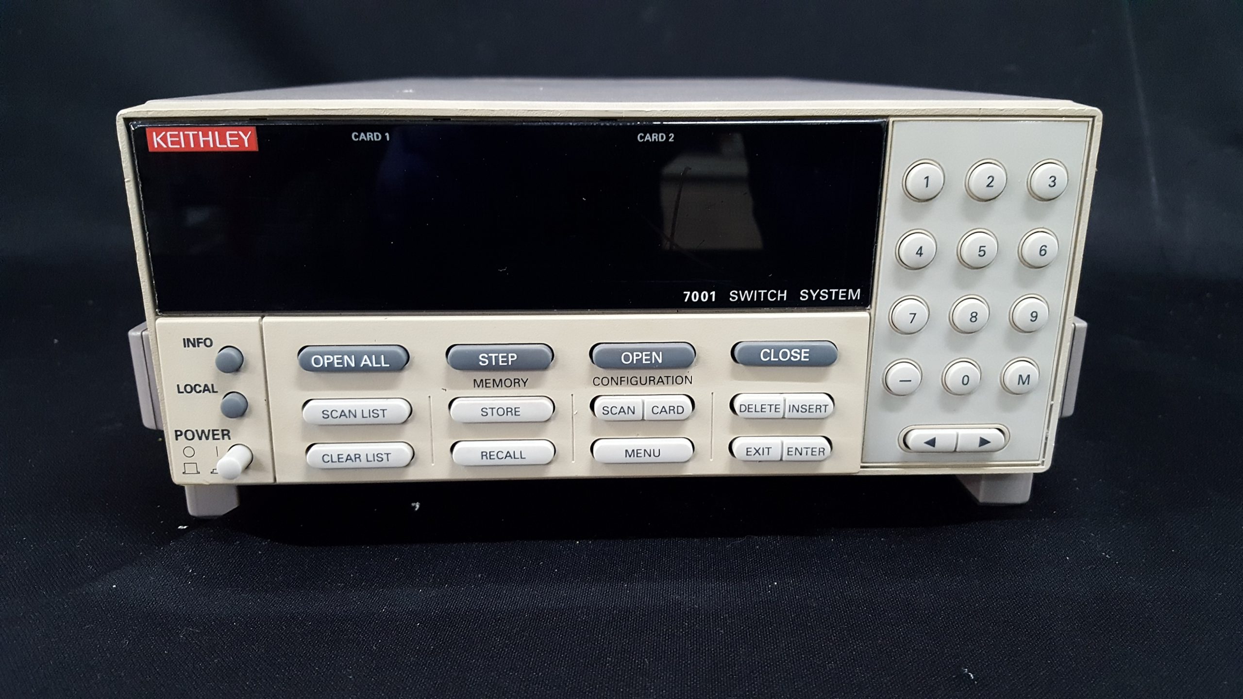
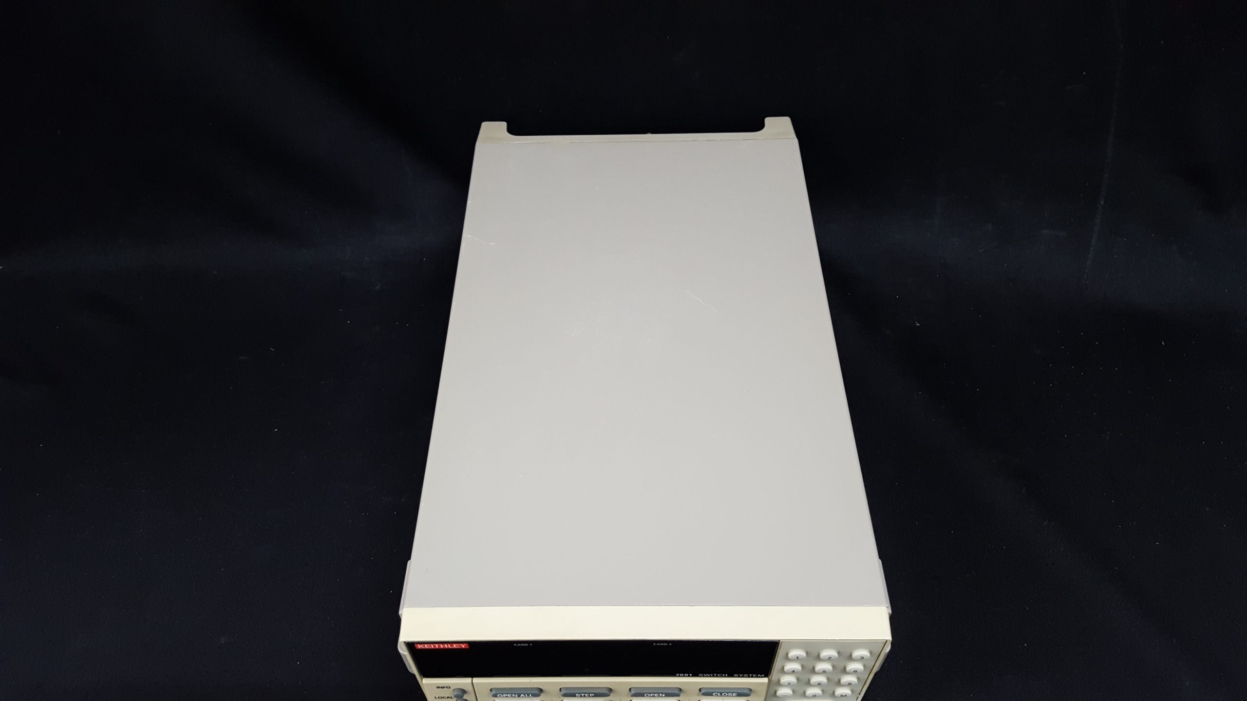
Keithley 7001 7012-S
- Model7001
- MakerKeithley
- DescriptionSwitch System
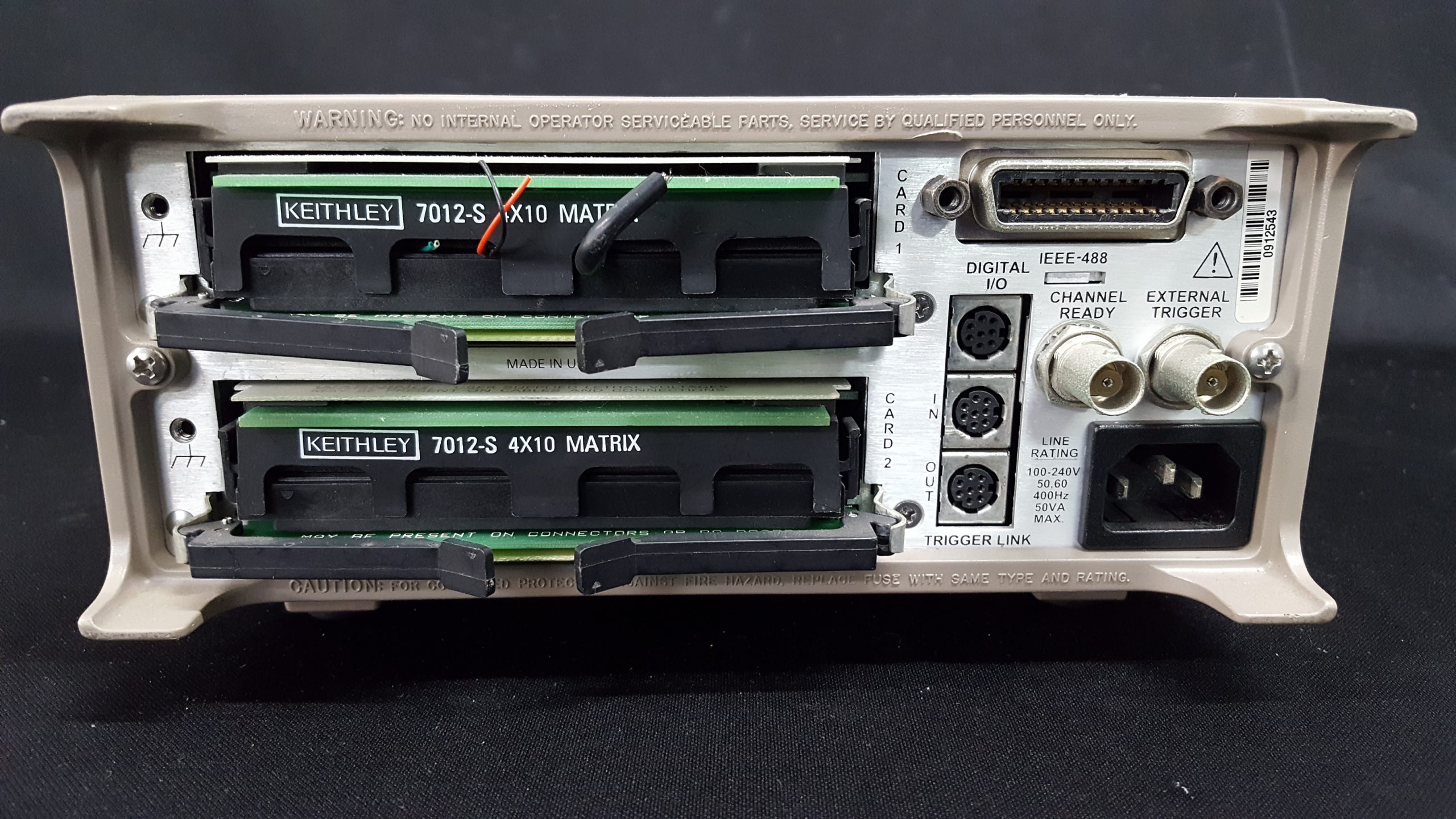
- Option47012-S
- Rental문의요망
- Stock문의요망
The Model 7001 is a half-rack, high density, two-slot mainframe that supports the widest range of signals in the test and measurement industry.
DC switching capabilities from nanovolts to 1100V and femtoamps to 5A,
as well as RF and optical switch support, make the Model 7001 a versatile
production test tool for a wide array of applications.
Built-in scan control eliminates the need for the computer to control every
step of the test procedure. Simply program the 7001 to control channel
spacing, scan spacing, and the number of scans. A built-in non-volatile
memory stores up to 100 complete switch patterns. You can include these
memory locations as part of the scan list.
Up to 80 channels of 2-pole switching. Each slot of the 7001 can
accommodate up to 40 channels. This means fewer switch cards are
required, reducing the amount of switching hardware needed. Higher density also provides extra
capacity and flexibility.
Analog backplane. The 7001’s analog backplane is used by the high density switch cards. The backplane eliminates intercard wiring and increases configuration flexibility. Two cards can be connected
through the backplane to create a 1×80 multiplexer, a 4×20 matrix, or a multiplexer/matrix combination that provides matrix row expansion.
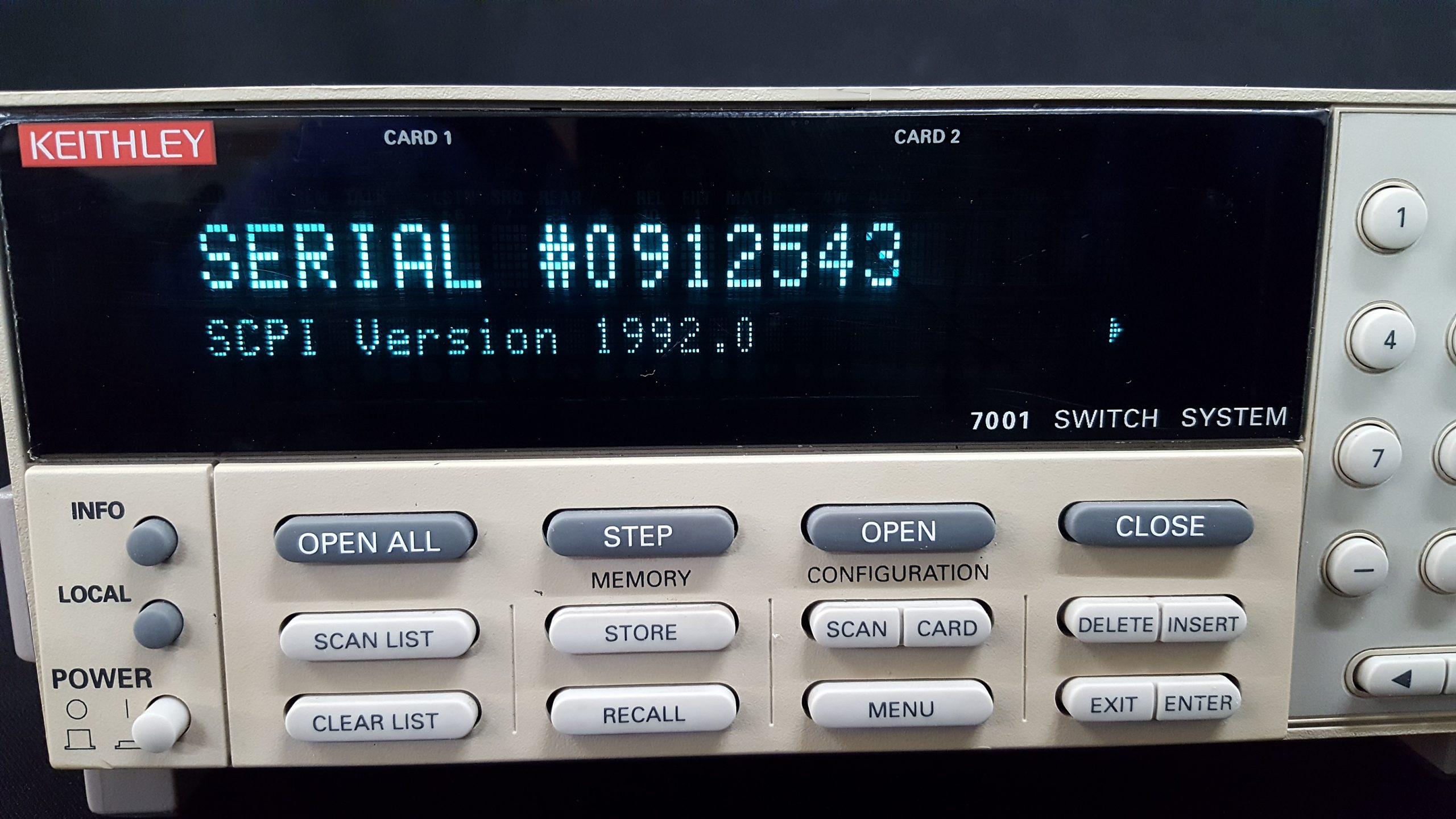
Channel status display. See the status of every channel simultaneously. The vacuum fluorescent
display of the 7001 shows the open/close status of each channel in the mainframe simultaneously. The
graphical display pattern makes it much easier to configure a test system, make modifications, or debug
an existing program. The status of the cards in both slots is displayed side by side on the same screen.
Easy to set up and use. The 7001 has a number of built-in features that make it easy to set up, run,
change, or modify. It conforms to IEEE-488.2 and SCPI (Standard Commands for Programmable Instruments).
All aspects of the instrument can be programmed from the front panel and over the IEEE bus.
Trigger Link. Trigger Link is a high speed trigger bus that provides simple trigger coordination
between the Model 7001 and other instruments. This bus eliminates GPIB communication delays
during scanning to increase overall system throughput dramatically.
17 switch/control cards available. The 7001 switch cards accommodate a broad range of signals,
maintain very high accuracy, and will not degrade signal quality. By minimizing signal errors, these
cards will prevent degradation due to offset voltage, isolation resistance, and leakage current.
With its broad range of available cards, the 7001 provides multi-pole switching. Cards such as the
7011 can be used in either 2- or 4-pole configuration. If a card does not have the pole capacity
required, the 7001 can still accommodate the application—just select the
CARD PAIR function. It allows the channel closures in both slots to be
synchronized for up to 8-pole switching.
System
CAPACITY: 2 plug-in cards per mainframe.
MEMORY: Battery backed-up storage for 100 switch patterns.
SWITCH SETTLING TIME: Automatically selected by the mainframe for each card. Additional time from 0 to 99999.999
seconds can be added in 1ms increments.
TRIGGER SOURCES:
External Trigger (TTL-compatible, programmable edge,
600ns minimum pulse, rear panel BNC).
IEEE-488 bus (GET, *TRG)
Trigger Link
Manual (front panel)
Internal Timer, programmable from 1ms to 99999.999
seconds in 1ms increments.
STATUS OUTPUT: Channel Ready (TTL-compatible signal,
rear panel BNC). Low going pulse (10µs typical) issued
after relay settling time. For two different switch cards,
7001 will be set to the slowest relay settling time.
SWITCHING SEQUENCE: Automatic break-before-make.
MAINFRAME DIGITAL I/O: 4 open-collector outputs
(30V maximum pull-up voltage, 100mA maximum sink
current, 10W output impedance), 1 TTL compatible input,
1 common.
RELAY DRIVE: 700mA maximum for both card slots.
CARD SIZE: 32mm high × 114mm wide × 272mm long (11
⁄4 in
× 4½ in × 103 ⁄4 in).
CARD COMPATIBILITY: Fully compatible with all
7XXX cards.
Throughput
EXECUTION SPEED OF SCAN LIST1:
7011 Card 7015 Card
Individual Channels: 130/second 500/second
Memory Setups: 125/second 450/second
TRIGGER EXECUTION TIME (maximum time from
activation of Trigger Source to start of switch open
or close2
):
Source Latency Jitter
GET3 200 µs <50 µs
*TRG3 5.0 ms
Trigger Link 200 µs <13 µs
External 200 µs <13 µs
Note s
1. Rates include switch settling time of cards: 3ms for 7011 and 500µs for
7015 cards.
2. Excluding switch settling time.
3. Assuming no IEEE-488 commands are pending execution.
IEEE-488 Command
Execution Time
Execution Time1
Command Display Off Display On
OPEN (@1!1) 7.5 ms 8.5 ms
CLOS (@1!1) 7.5 ms 8.5 ms
MEM:REC M1 5.0 ms 6.0 ms
Note s
1. Measured from the time at which the command terminator is taken
from the bus to the time at which the relay begins to open or close