리퍼비시 계측기
리퍼비시 계측기
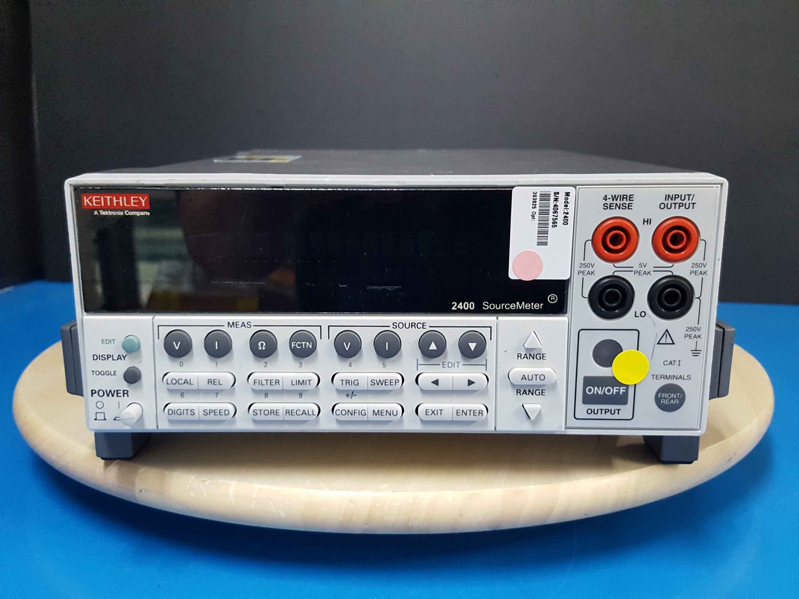
Keithley’s Series 2400 Source Measure Unit (SMU) Instruments are designed specifically for test applications that demand tightly coupled sourcing and measurement. All SourceMeter models provide precision voltage and current sourcing as well as measurement capabilities. Each SourceMeter SMU instrument is both a highly stable DC power source and a true instrument-grade 6½-digit multimeter. The power source characteristics include low noise, precision, and readback. The multimeter capabilities include high repeatability and low noise. The result is a compact, single-channel, DC parametric tester. In operation, these instruments can act as a voltage source, a current source, a voltage meter, a current meter, and an ohmmeter. Manufacturers of components and modules for the communications, semiconductor, computer, automotive, and medical industries will find the SourceMeter SMU instruments invaluable for a wide range of characterization and production test applications.
Key Features
- Five instruments in one (IV Source, IVR Measure)
- Five models: 20–100 W DC, 1000 W pulsed, 1100 V to 1 µV
- Source and sink (4-quadrant) operation
- 0.012% basic measure accuracy with 6½-digit resolution
- 2-, 4-, and 6-wire remote V-source and measure sensing
- 1700 readings/second at 4½ digits via GPIB
- Pass/Fail comparator for fast sorting/binning
- Programmable DIO port for automation/handler/prober control (except 2401)
- Standard SCPI GPIB, RS-232 and Keithley Trigger Link interfaces
- Download KickStart today and try it out for 60 days
Advantages of a Tightly Integrated Instrument
By linking source and measurement circuitry in a single unit, these instruments offer a variety of advantages over systems configured with separate source and measurement instruments. For example, they minimize the time required for test station development, setup, and maintenance, while lowering the overall cost of system ownership. They simplify the test process itself by eliminating many of the complex synchronization and connection issues associated with using multiple instruments. And, their compact half-rack size conserves precious “real estate” in the test rack or bench.
|
del |
Range |
Programming Resolution |
Source 1 Accuracy (1 Year)23°C ±5°C±(% rdg. + volts) |
Default Measurement Resolution |
Measurement 2, 3, 4 Accuracy (1 Year)23°C ±5°C±(% rdg. + volts) |
Output Slew Rate (±30%) |
Source/Sink Limit |
|
2400, 2401 |
200.000 mV |
5 µV |
0.02% + 600 µV |
1 µV |
0.012% + 300 µV |
±21 V @ ±1.05 A ±210 V @ ±105 mA* |
|
|
2.00000 V |
50 µV |
0.02% + 600 µV |
10 µV |
0.012% + 300 µV |
|
||
|
20.0000 V |
500 µV |
0.02% + 2.4 mV |
100 µV |
0.015% + 1.5 mV |
0.08 V/µs |
||
|
200.000 V* |
5 mV |
0.02% + 24 mV |
1 mV |
0.015% + 10 mV |
0.5 V/µs |
||
|
2410 |
200.000 mV |
5 µV |
0.02% + 600 µV |
1 µV |
0.012% + 300 µV |
±21 V @ ±1.05 A ±1100 V @ ±21 mA |
|
|
2.00000 V |
50 µV |
0.02% + 600 µV |
10 µV |
0.012% + 300 µV |
|
||
|
20.0000 V |
500 µV |
0.02% + 2.4 mV |
100 µV |
0.015% + 1 mV |
0.15 V/µs |
||
|
1000.00 V |
50 mV |
0.02% + 100 mV |
10 mV |
0.015% + 50 mV |
0.5 V/µs |
||
|
2420 |
200.000 mV |
5 µV |
0.02% + 600 µV |
1 µV |
0.012% + 300 µV |
±21 V @ ±3.15 A ±63 V @ ±1.05 A |
|
|
2.00000 V |
50 µV |
0.02% + 600 µV |
10 µV |
0.012% + 300 µV |
|
||
|
20.0000 V |
500 µV |
0.02% + 2.4 mV |
100 µV |
0.015% + 1 mV |
0.08 V/µs |
||
|
60.0000 V |
1.5 mV |
0.02% + 7.2 mV |
1 mV |
0.015% + 3 mV |
0.14 V/µs |
||
|
2440 |
200.000 mV |
5 µV |
0.02% + 600 µV |
1 µV |
0.012% + 300 µV |
±10.5 V @ ±5.25 A ±42 V @ ±1.05 A |
|
|
2.00000 V |
50 µV |
0.02% + 600 µV |
10 µV |
0.012% + 300 µV |
|
||
|
10.0000 V |
500 µV |
0.02% + 1.2 mV |
100 µV |
0.015% + 750 µV |
0.08 V/µs |
||
|
40.0000 V |
5 mV |
0.02% + 4.8 mV |
1 mV |
0.015% + 3 mV |
0.25 V/µs |
||
|
*Not available on 2401. |
|||||||
NOTES
- 2400, 2401, 2410 Only: Specifications valid for continuous output currents below 105 mA. For operation above 105 mA continuous for >1 minute, derate accuracy 10%/35 mA above 105 mA.
- Speed = Normal (1 PLC). For 0.1 PLC, add 0.005% of range to offset specifications, except 200 mV, 1 A, 10 A ranges, add 0.05%. For 0.01 PLC, add 0.05% of range to offset specifications, except 200 mV, 1 A, 10 A ranges, add 0.5%.
- Accuracies apply to 2- or 4-wire mode when properly zeroed.
- In pulse mode, limited to 0.1 PLC measurement.
Temperature Coefficient (0°–18°C and 28°–50°C) — ±(0.15 × accuracy specification)/°C.
Voltage Regulation — Line: 0.01% of range. Load: 0.01% of range + 100 µV.
Over Voltage Protection — User selectable values, 5% tolerance. Factory default = none.
Current Limit — Bipolar current limit (compliance) set with single value. Min. 0.1% of range.
Overshoot — <0.1% typical (full scale step, resistive load, 10 mA range).
Additional Source Specifications (All Models)
Transient Response Time — 30 µs minimum for the output to recover to its spec. following a step change in load.
Command Processing Time — Maximum time required for the output to begin to change following the receipt of :SOURce:VOLTage|CURRent command. Autorange On: 10 ms. Autorange Off: 7 ms.
Output Settling Time — Time required to reach 0.1% of final value after command is processed. 100 µs typical. Resistive load. 10 µA to 100 mA range.
DC Floating Voltage — Output can be floated up to ±250 VDC (2440 ±40 VDC) from chassis ground.
Remote Sense — Up to 1 V drop per load lead.
Compliance Accuracy — Add 0.3% of range and ±0.02% of reading to base specification.
Over Temperature Protection — Internally sensed temperature overload puts unit in standby mode.
Range Change Overshoot — Overshoot into a fully resistive 100 kΩ load, 10 Hz to 1 MHz BW, adjacent ranges: 100 mV typical, except 20 V/200 V (20 V/60 V on 2420), range boundary, and 2440.
Minimum Compliance Value — 0.1% of range.
Current Accuracy (Local or Remote Sense)
|
Model |
Range |
Programming Resolution |
Source 1, 3Accuracy(1 Year)23°C ±5°C±(% rdg. + amps) |
Default Measurement Resolution |
Measurement 5, 6, 7Accuracy (1 Year)23°C ±5°C±(% rdg. + amps) |
Source/Sink Limit |
|
2400, 2401 |
1.00000 µA |
50 pA |
0.035% + 600 pA |
10 pA |
0.029% + 300 pA |
±1.05A @ ±21 V ±105 mA @ ±210 V8 |
|
10.0000 µA |
500 pA |
0.033% + 2 nA |
100 pA |
0.027% + 700 pA |
||
|
100.000 µA |
5 nA |
0.031% + 20 nA |
1 nA |
0.025% + 6 nA |
||
|
1.00000 mA |
50 nA |
0.034% + 200 nA |
10 nA |
0.027% + 60 nA |
||
|
10.0000 mA |
500 nA |
0.045% + 2 µA |
100 nA |
0.035% + 600 nA |
||
|
100.000 mA |
5 µA |
0.066% + 20 µA |
1 µA |
0.055% + 6 µA |
||
|
1.00000 A2 |
50 µA |
0.27 % + 900 µA |
10 µA |
0.22 % + 570 µA |
||
|
2410 |
1.00000 µA |
50 pA |
0.035% + 600 pA |
10 pA |
0.029% + 300 pA |
±1.05A @ ±21 V ±21 mA @ ±1100 V |
|
10.0000 µA |
500 pA |
0.033% + 2 nA |
100 pA |
0.027% + 700 pA |
||
|
100.000 µA |
5 nA |
0.031% + 20 nA |
1 nA |
0.025% + 6 nA |
||
|
1.00000 mA |
50 nA |
0.034% + 200 nA |
10 nA |
0.027% + 60 nA |
||
|
20.0000 mA |
500 nA |
0.045% + 4 µA |
100 nA |
0.035% + 1.2 µA |
||
|
100.000 mA |
5 µA |
0.066% + 20 µA |
1 µA |
0.055% + 6 µA |
||
|
1.00000 A2 |
50 µA |
0.27 % + 900 µA |
10 µA |
0.22 % + 570 µA |
||
|
2420 |
10.0000 µA |
500 pA |
0.033% + 2 nA |
100 pA |
0.027% + 700 pA |
±3.15A @ ±21 V ±1.05 A @ ±63 V |
|
100.000 µA |
5 nA |
0.031% + 20 nA |
1 nA |
0.025% + 6 nA |
||
|
1.00000 mA |
50 nA |
0.034% + 200 nA |
10 nA |
0.027% + 60 nA |
||
|
10.0000 mA |
500 nA |
0.045% + 2 µA |
100 nA |
0.035% + 600 nA |
||
|
100.000 mA |
5 µA |
0.066% + 20 µA |
1 µA |
0.055% + 6 µA |
||
|
1.00000 A2 |
50 µA |
0.067% + 900 µA |
10 µA |
0.066% + 570 µA |
||
|
3.00000 A2 |
50 µA |
0.059% + 2.7 mA |
10 µA |
0.052% + 1.71 mA |
||
|
2440 |
10.0000 µA |
500 pA |
0.033% + 2 nA |
100 pA |
0.027% + 700 pA |
±5.25A @ ±10.5 V ±1.05 A @ ±42 V |
|
100.000 µA |
5 nA |
0.031% + 20 nA |
1 nA |
0.025% + 6 nA |
||
|
1.00000 mA |
50 nA |
0.034% + 200 nA |
10 nA |
0.027% + 60 nA |
||
|
10.0000 mA |
500 nA |
0.045% + 2 µA |
100 nA |
0.035% + 600 nA |
||
|
100.000 mA |
5 µA |
0.066% + 20 µA |
1 µA |
0.055% + 6 µA |
||
|
1.00000 A |
50 µA |
0.067% + 900 µA |
10 µA |
0.060% + 570 µA |
||
|
5.00000 A |
50 µA |
0.10 % + 5.4 mA |
10 µA |
0.10 % + 3.42 mA |
NOTES
- 2400, 2401, 2410 Only: Specifications valid for continuous output currents below 105 mA. For operation above 105 mA continuous for >1 minute, derate accuracy 10%/35 mA above 105 mA.
- Full operation (1 A) regardless of load to 30°C (50°C for 2420 and 2440). Above 30°C (50°C for 2420 and 2440) ambient, derate 35 mA/°C and prorate 35 mA/Ω load. 4-wire mode. For current sink operation on 1 A, 3 A, or 5 A ranges, maximum continuous power is limited to approximately 1/2 rated power or less, depending on current, up to 30°C ambient. See power equations in the User’s Manual to calculate allowable duty cycle for specific conditions.
- For sink mode, 1 µA to 100 mA range, accuracy is: 2400, 2401: ±(0.15% + offset*4). 2410, 2420, 2440: ±(0.5% + offset*3).For 1A range, accuracy is: 2400, 2401: ±(1.5% + offset*8). 2410, 2420, 2440: ±(1.5% + offset*3).
- 10 A range only in pulse mode. Limited to 2.5 ms pulse width maximum. 10% duty cycle maximum.
- Speed = Normal (1 PLC). For 0.1 PLC, add 0.005% of range to offset specifications, except 200 mV, 1 A, 10 A ranges, add 0.05%. For 0.01 PLC, add 0.05% of range to offset specifications, except 200 mV, 1 A, 10 A ranges, add 0.5%.
- Accuracies apply to 2- or 4-wire mode when properly zeroed.
- In pulse mode, limited to 0.1 PLC measurement.
- 2400 only.
Temperature Coefficient (0°–18°C and 28°–50°C) — ±(0.15 × accuracy specification)/°C.
Current Regulation — Line: 0.01% of range. Load: 0.01% of range (except 2440 5 A range 0.05%) + 100 pA.
Voltage Limit — Bipolar voltage limit (compliance) set with single value. Min. 0.1% of range.
Overshoot — <0.1% typical (1 mA step, RL = 10 kΩ, 20 V range for 2400, 2401, 2410, 2420), (10 V range for 2440).
Resistance Measurement Accuracy (Local or Remote Sense) 1, 2, 5
|
Range |
Default Resolution |
Default Test Current 2400, 2401, 2410 |
Default Test Current 2420, 2440 |
Normal Accuracy (23°C ±5°C)1 Year, ±(% rdg. + ohms) |
Enhanced Accuracy(23°C ±5°C)41 Year, ±(% rdg. + ohms) |
||
|
2400, 2401 |
2410 |
2420, 2440 |
2400, 2401 |
||||
|
<0.20000 Ω3 |
– |
– |
– |
Source IACC + Meas. VACC |
Source IACC + Meas. VACC |
Source IACC + Meas. VACC |
Source IACC + Meas. VACC |
|
2.00000 Ω3 |
10 µΩ |
– |
1 A |
Source IACC + Meas. VACC |
Source IACC + Meas. VACC |
0.17% + 0.0003 Ω |
Source IACC + Meas. VACC |
|
20.0000 Ω |
100 µΩ |
100 mA |
100 mA |
0.10% + 0.003 Ω |
0.11% + 0.006 Ω |
0.10% + 0.003 Ω |
0.07% + 0.001 Ω |
|
200.000 Ω |
1 mΩ |
10 mA |
10 mA |
0.08% + 0.03 Ω |
0.09% + 0.1 Ω |
0.08% + 0.03 Ω |
0.05% + 0.01 Ω |
|
2.00000 kΩ |
10 mΩ |
1 mA |
1 mA |
0.07% + 0.3 Ω |
0.08% + 0.6 Ω |
0.07% + 0.3 Ω |
0.05% + 0.1 Ω |
|
20.0000 kΩ |
100 mΩ |
100 µA |
100 µA |
0.06% + 3 Ω |
0.07% + 6 Ω |
0.06% + 3 Ω |
0.04% + 1 Ω |
|
200.000 kΩ |
1 Ω |
10 µA |
10 µA |
0.07% + 30 Ω |
0.07% + 60 Ω |
0.07% + 30 Ω |
0.05% + 10 Ω |
|
2.00000 MΩ6 |
10 Ω |
1 µA |
1 µA |
0.11% + 300 Ω |
0.12% + 600 Ω |
0.11% + 300 Ω |
0.05% + 100 Ω |
|
20.0000 MΩ7 |
100 Ω |
1 µA |
1 µA |
0.11% + 1 kΩ |
0.12% + 2.4 kΩ |
0.11% + 1 kΩ |
0.05% + 500 Ω |
|
200.000 MΩ3 |
1 kΩ |
100 nA |
– |
0.66% + 10 kΩ |
0.66% + 24 kΩ |
Source IACC + Meas. VACC |
0.35% + 5 kΩ |
|
>200.000 MΩ3 |
– |
– |
– |
Source IACC + Meas. VACC |
Source IACC + Meas. VACC |
Source IACC + Meas. VACC |
Source IACC + Meas. VACC |
Temperature Coefficient (0°–18°C and 28°–50°C) — ±(0.15 × accuracy specification)/°C.
Source I Mode, Manual Ohms — Total uncertainty = I source accuracy + V measure accuracy (4-wire remote sense).
Source V Mode, Manual Ohms — Total uncertainty = V source accuracy + I measure accuracy (4-wire remote sense).
6-wire Ohms Mode — Available using active ohms guard and guard sense. Max. Guard Output Current: 50 mA (except 1 A range). Accuracy is load dependent. Refer to White Paper below for calculation formula: “Obtaining More Accurate Resistance Measurements Using the 6-wire Ohms Measurement Technique.”
Guard Output Impedance — <0.1Ω in ohms mode.
NOTES
- Speed = Normal (1 PLC). For 0.1 PLC, add 0.005% of range to offset specifications, except 200 mV, 1 A, 10 A ranges, add 0.05%. For 0.01 PLC, add 0.05% of range to offset specifications, except 200 mV, 1 A, 10 A ranges, add 0.5%.
- Accuracies apply to 2- or 4-wire mode when properly zeroed.
- Manual ohms only – except 2420, 2440 for 2 Ω range and 2400, 2401, or 2410 for 200 MΩ range.
- Source readback enabled, offset compensation ON. Also available on 2410, 2420, and 2440 with similar accuracy enhancement.
- In pulse mode, limited to 0.1 PLC measurement.
- Except 2440; default test current is 5 µA.
- Except 2440; default test current is 0.5 µA.
System Speeds
Measurement 1
Maximum Range Change Rate — 75/second.
Maximum Measure Autorange Time40 ms (fixed source).2
Sweep Operation3 Reading Rates (rdg./second) for 60 Hz (50 Hz)
|
Speed |
NPLC/Trigger Origin |
Measure |
Source-Measure |
Source-Measure5Pass/Fail Test4, 5 |
Source-Memory4 |
||||||||||||
|
To Mem. |
To GPIB |
To Mem. |
To GPIB |
To Mem. |
To GPIB |
To Mem. |
To GPIB |
||||||||||
|
Fast |
0.01 / internal |
2081 |
(2030) |
1754 |
1551 |
(1515) |
1369 |
902 |
(900) |
981 |
165 |
(162) |
165 |
||||
|
IEEE-488.1 Mode |
0.01 / external |
1239 |
(1200) |
1254 |
1018 |
(990) |
1035 |
830 |
(830) |
886 |
163 |
(160) |
163 |
||||
|
Fast |
0.01 / internal |
2081 |
(2030) |
1198 |
(1210) |
1551 |
(1515) |
1000 |
(900) |
902 |
(900) |
809 |
(840) |
165 |
(162) |
164 |
(162) |
|
IEEE-488.2 Mode |
0.01 / external |
1239 |
(1200) |
1079 |
(1050) |
1018 |
(990) |
916 |
(835) |
830 |
(830) |
756 |
(780) |
163 |
(160) |
162 |
(160) |
|
Medium |
0.10 / internal |
510 |
(433) |
509 |
(433) |
470 |
(405) |
470 |
(410) |
389 |
(343) |
388 |
(343) |
133 |
(126) |
132 |
(126) |
|
IEEE-488.2 Mode |
0.10 / external |
438 |
(380) |
438 |
(380) |
409 |
(360) |
409 |
(365) |
374 |
(333) |
374 |
(333) |
131 |
(125) |
131 |
(125) |
|
Normal |
1.00 / internal |
59 |
(49) |
59 |
(49) |
58 |
(48) |
58 |
(48) |
56 |
(47) |
56 |
(47) |
44 |
(38) |
44 |
(38) |
|
IEEE-488.2 Mode |
1.00 / external |
57 |
(48) |
57 |
(48) |
57 |
(48) |
57 |
(47) |
56 |
(47) |
56 |
(47) |
44 |
(38) |
44 |
(38) |
Single Reading Operation Reading Rates (rdg./second) for 60 Hz (50 Hz)
|
Speed |
NPLC/Trigger Origin |
Measure To GPIB |
Source-Measure5 To GPIB |
Source-Measure Pass/Fail Test4, 5 To GPIB |
|||
|
Fast (488.1) |
0.01 / internal |
537 |
140 |
135 |
|||
|
Fast (488.2) |
0.01 / internal |
256 |
(256) |
79 |
(83) |
79 |
(83) |
|
Medium (488.2) |
0.10 / internal |
167 |
(166) |
72 |
(70) |
69 |
(70) |
|
Normal (488.2) |
1.00 / internal |
49 |
(42) |
34 |
(31) |
35 |
(30) |
Component for 60 Hz (50 Hz) 4, 6
|
Speed |
NPLC/Trigger Origin |
Measure To GPIB |
Source Pass/Fail Test |
Source-Measure Pass/Fail Test5, 7To GPIB |
|||
|
Fast |
0.01 / external |
1.04 ms |
(1.08 ms) |
0.5 ms |
(0.5 ms) |
4.82 ms |
(5.3 ms) |
|
Medium |
0.10 / external |
2.55 ms |
(2.9 ms) |
0.5 ms |
(0.5 ms) |
6.27 ms |
(7.1 ms) |
|
Normal |
1.00 / external |
17.53 ms |
(20.9 ms) |
0.5 ms |
(0.5 ms) |
21.31 ms |
(25.0 ms) |
NOTES
- Reading rates applicable for voltage or current measurements. Auto zero off, autorange off, filter off, display off, trigger delay = 0, and binary reading format.
- Purely resistive lead. 1 µA and 10 µA ranges <65 ms.
- 1000 point sweep was characterized with the source on a fixed range.
- Pass/Fail test performed using one high limit and one low math limit.
- Includes time to re-program source to a new level before making measurement.
- Time from falling edge of START OF TEST signal to falling edge of end of test signal.
- Command processing time of :SOURce:VOLTage|CURRent:TRIGgered command not included.
General Specifications
Noise Rejection —
|
NPLC |
NMRR |
CMRR |
|
|
Fast |
0.01 |
— |
80 dB |
|
Medium |
0.1 |
— |
80 dB |
|
Slow |
1 |
60 dB |
100 dB1 |
|
1 Except lowest 2 current ranges = 90dB. |
|||
Load Impedance — Stable into 20,000 pF typical.
Common Mode Voltage — 250 V DC (40V DC for 2440).
Common Mode Isolation — >109Ω, <1000pF.
Overrange — 105% of range, source and measure.
Max. Voltage Drop Between Input/Output and Sense Terminals — 5 V.
Max. Sense Lead Resistance — 1 MΩ for rated accuracy.
Sense Input Impedance — >1010Ω.
Guard Offset Voltage — <150 µV, typical (300 µV for 2440).
Source Output Modes — Fixed DC levelMemory List (mixed function)Stair (linear and log)
Memory Buffer — 5,000 readings @ 5 digits (two 2,500 point buffers). Includes selected measured value(s) and time stamp. Lithium battery backup (3 yr+ battery life).
Source Memory List — 100 points max.
Programmability — IEEE-488 (SCPI-1995.0), RS-232, 5 user-definable power-up states plus factory default and *RST.
Digital Interface
Output Enable — Active low input.
Handler Interface — Start of test, end of test, 3 category bits. +5 V @ 300 mA supply. Not available on 2401.
Digital I/O — 1 trigger input, 4 TTL/Relay Drive outputs (33 V @ 500 mA, diode clamped). Not available on 2401.
Power Supply — 100 V to 240 V rms, 50–60 Hz (automatically detected at power up). 2400, 2401: 190 VA. 2410: 210 VA. 2420: 220 VA. 2440: 240VA.
Cooling — 2401: Convection. 2410, 2420, 2440: Forced air, variable speed.
EMC — Conforms to European Union Directive 89/336/EEC, EN 61326-1.
Safety — Conforms to European Union Low Voltage Directive. 2400 and 2401 UL listed to UL 61010-1:2012 and UL 61010-2-30:2012.
Vibration — MIL-PRF-28800F Class 3 Random.
Warm-Up — 1 hour to rated accuracies.
Dimensions — 89 mm high × 213 mm wide × 370 mm deep (3½ in × 83⁄8 in × 149⁄16 in). Bench Configuration (with handle and feet): 104 mm high × 238 mm wide × 370 mm deep (41⁄8 in × 93⁄8 in × 149⁄16 in).
Weight — 3.21 kg (7.08 lbs.) (2440: 4.1kg, 9.0 lbs).
Environment — Operating: 0°–50°C, 70% R.H. up to 35°C. Derate 3% R.H./°C, 35°–50°C. Storage: –25°C to 65°C.